Showing posts with label Games. Show all posts

Monday, 25 August 2014

Dangerous caterpillars solution

Figure 1. The usual suspects.
Last time I asked if we could work out which caterpillars from Figure 1 are safe based on the following rules:
  1. If a caterpillar has blue eyes or spots it is dangerous. If a caterpillar has both, we can't tell if it is dangerous.
  2. All safe caterpillars have more than one of the following features: teeth, blue eyes, spots, or spikes.
  3. Caterpillars with both teeth and spots are dangerous.
As I suggested Venn diagrams are expertly suited to this kind of puzzle. 

To solve the puzzle using Venn diagrams we, first, decide what our sets are going to be. In the clues there are 4 features that are discussed: teeth, blue eyes, spots and spikes. Thus, we construct a Venn diagram of these four qualities and insert the caterpillars to their appropriate spaces. This can be seen in Figure 2. Note that in this specific problem we have to use the full Venn diagram form of the four sets, rather than the Euler diagram that we discussed, previously.
Figure 2. Separating the caterpillars into types.
Now that we have our diagram we use the clues to remove sections and restrict the safe caterpillar possibilities.

The simplified Venn diagrams corresponding to each of the clues can be seen in Figure 3. For example, the first clue states that animals with blue eyes and spots (but, perhaps, not both) are dangerous. Thus, we remove the sections corresponding to the blue eyed caterpillars and the spots. However, the region over which they intersect is left, because we can't be sure if those caterpillars are dangerous or not.
Figure 3. Removing sections of the Venn diagram based on the clues. Left: the blanked out section corresponds to either having blue eyes or spots, but not both. Center: removing the sections with only one feature. Right: removing the section with teeth and spots.
This process is carried out for all three clues. Finally, we put together only the sections that remain in all three diagrams in Figure 3 to get Figure 4.
Figure 4. Only one caterpillar left.
As you see will from Figure 4 there are only 3 sections of the Venn diagram left. These include two sections in the blue eyes and spots region. Because of rule 1, we cannot tell if those sections are safe, or not. Luckily, there are no caterpillars in these regions, so no risks need be taken. The only caterpillar left has both spikes and teeth... would you trust this guy?

Monday, 11 August 2014

More Venn diagrams with a logic puzzle

A long time ago I posted about Venn and Euler diagrams and I have been meaning to get back to this subject. Coincidentally, it was John Venn's 180th birthday on the 4th of August, celebrated by Google, so I cannot think of a better time to revive the subject.

Firstly, we recall the all important definition: a Venn diagram contains every single possible intersection between all combinations of the sets. This can be compared with an Euler diagram, which only shows the intersections in which you are interested. An illustration of this can be found in Figure 1.
Figure 1. Using four shapes a basic Euler diagram is not the same as a Venn diagram. The right shows an Euler diagram whereas the left is a Venn diagram, as it contains all possible combinations of the four groups.
As I mentioned, these are great ways of seeing logical information quickly and clearly. To show how useful they are let us consider the following puzzle.
________________________________________________________________
________________________________________
I have a collection of 8 caterpillars that have a range of different features. They can all be seen in Figure 2, below.
Unfortunately, some of them are dangerous to touch. Equally troubling is that I do not know which the dangerous ones are! All I know is that the following three statements are true:
  1. If a caterpillar has blue eyes or spots it is dangerous. If a caterpillar has both, we can't tell if it is dangerous.
  2. All safe caterpillars have more than one of the following features: teeth, blue eyes, spots, or spikes.
  3. Caterpillars with both teeth and spots are dangerous.
Using just these facts, which caterpillars are safe to touch?

Now of course there are many ways to solve this little puzzle, but Venn diagrams offer a really nifty way of seeing the solution simply and completely. Have a go at solving it and I'll post the solution next time.

Monday, 21 April 2014

Rotationally symmetric Venn diagrams

No doubt you will have seen a Venn diagram. They are a wonderful way of presenting logical information. For example, they allow us to illustrate the fact that centaurs lie in the union of objects with male torsos and horse legs (Figure 1).
Figure 1. Not all male torsos are connected to horse legs and vice versa. However, we see that centaurs do lie in the intersection.
Recently there has been an upsurge in using Venn diagrams as way of illustrating jokes, or song titles. My personal favourite explains where the platypus fits in the animal kingdom (Figure 2).
Figure 2. Although not scientifically sound it does show that the keyboard guitar and platypus can be defined as the intersection of two other sets.
Of course you are not restricted to two sets of objects. A Venn diagram can be made of any number of sets. For example Figure 3 illustrates the some of the lyrics from the song “The Joker” by the Steve Miller Band.
Figure 3. A seven set intersection diagram illustrating the characteristics of certain famous people.
Technically, Figure 3 illustrates an Euler diagram and not a Venn diagram. A Venn diagram contains every single possible intersection between all combinations of the sets, whereas an Euler diagram only shows the intersections you are interested in. For example, in Figure 3 there is no section where only grinners and jokers intersect (this could possible contain Heath Ledger).

When dealing with two or three sets the obvious Euler diagram is also a Venn diagram (Figure 4). Interestingly, they both also have rotational symmetry. This will be considered in more detail in the next article.
Figure 4. Two and three set Venn diagrams.
However, when we get to four circles, things are not so easy anymore and the basic Euler diagram (Figure 5, left) is no longer a Venn diagram. However, by removing the restriction that the groups have to be circles we can once again produce a four set Venn diagram (Figure 5, right). Sadly though, we have lost the pleasing rotational symmetry.
Figure 5. If only circular shapes are used we cannot create a Venn diagram, only an Euler diagram (left). However, by generalizing the set's shape, we can produce a Venn diagram once more (right).
Next time I will present another part of the discussion with Barry Cipra and we will see under what conditions Venn diagrams can have rotational symmetry.

Monday, 7 April 2014

Sol LeWitt Solution


Last time I introduced the Sol LeWitt’s problem, devised by the eminent mathematical reporter Barry Cipra. The challenge was to take the tiles, as presented in the left image of Figure 1 and rearrange them such that all the lines form continuous rows, columns and diagonals across the grid. As I revealed there are many solutions, one such solution is presented in the right image of Figure 1.
Figure 1. Left: the original Sol LeWitt tiles. Right: an arrangement in which all lines cross the entire grid.
I also mentioned that there were some special relationships between certain solutions. For example rotating a solution through 90 degrees, reflecting it, or performing a combination of these two operations generates another, related solution. Furthermore, we can take the topmost row (or the leftmost column) and moving it all the way to the bottom (or to the right). Explicitly, a set of solutions can be drawn on the surface of a torus.

This leaves us with a new question. Are there any solutions which cannot be generated in such a way? Namely, starting from one solution are their other “distinct” solutions, which cannot be created through rotations, reflections or row/column operations. Each distinct solution will then generate a different solution set, which will lead to different to tori.

The famous mathematician John Conway demonstrated that there are actually three distinct solutions, from which all others can be derived. One has been given above. Can you find the other two possible distinct solutions?

As I was talking to Barry about this puzzle he told me a nice anecdote, where he had used this puzzle in a workshop involving maths teachers and maths researchers that had been paired together. He said that the teachers were constantly moving the pieces around, effectively using trial and error, whilst their researcher partner would sit back and think about the pieces. Eventually, one researcher claimed that the puzzle was impossible, not a moment later his partner produced a working solution! Let this be a lesson to any mathematician. Theory is all well and good, but practical intuition is invaluable.

Monday, 24 March 2014

The Sol LeWitt puzzle

One of my favourite puzzles created by Barry Cipra was originally not a maths puzzle at all. The puzzle is based on a design by artist Solomon LeWitt. Sol LeWitt (after whom the puzzle is named) was a conceptual artist who often featured geometric and combinatorial themes to give a minimalist style to his works. His etching picture, titled Straight Lines in Four Directions and All Their Possible Combinations, is illustrated below in Figure 1, on the left.

Figure 1. Left: the Sol LeWitt tiles. Right: an example of a red line connecting the edges through all the tiles and an example of a blue line that does not.

To everyone except Barry this image simply showed 16 squares with lines drawn on them. However, Barry’s imagination was ignited when he noticed that some of the lines extend continuously from one side of the large square to another (red diagonal line in the right-hand of Figure 1), whilst others do not (blue horizontal line in the right-hand of Figure 1).

From this simple setting Barry asked the question:
"Is it possible to rearrange the tiles such that the resulting 4x4 grid has a pattern that allows all horizontal, vertical and diagonal lines to extend continuously across the grid, without interruption?"
 Importantly, you are not allowed to rotate any of the pieces!

The simple answer is yes, you can produce such a pattern. In fact there are quite a few solutions to the problem! Have a go yourself. Cut out the squares and see you if can find one of them. Although finding one solution is satisfying, the more interesting investigation is finding a link between solutions.

Produce a few solutions and see if you can see some relation between them. Once you spot the link you will see how to produce many more solutions very easily. Not bad for a simple work of art!

Next time I will fill in the rest of the details, by presenting not only a solution but also furnishing you with the solution link that I am alluding to.
Good luck

Monday, 3 June 2013

Facing the Challenge of the Puzzle Museum.

Mathematics has the reputation of being an esoteric science wrapped up in theoretical objects that have no place in the physical world. But what is mathematics if not a huge elaborate game? You lay down your rules (axioms) at the start, set up your pieces (algebraic structure) and follow the game until you reach the end (solve your problem).

With this in mind Alain Goriely, Jon Chapman, Derek Moulton, Thomas Lessinnes and myself journeyed all the way to Devon to meet the wonderful James Dalgety, curator of the world’s biggest collection of puzzles and related ephemera. Our goal was to discover pieces amongst James’ 50,000+ puzzles that highlighted and demonstrated key mathematical ideas in a physical manner and, thus, could be used to form the basis of a puzzle exhibition in honour of the opening of the new University of Oxford Mathematical Institute.
Figure 1. James (centre) presenting just a small fraction of his entire collection to admiring crowd of (left to right) Derek, Alain, Jon and Thomas.
James’ tour through his house-cum-gallery took over four hours and spanned three large rooms, which were filled to bursting point with every conceivable puzzle type. Simply put, we were kids in a candy shop! Although we saw a great number of puzzles and even had a chance to try out our problem solving abilities, we hardly scratched the surface of his entire collection as beneath every full cabinet was a set of drawers, each carefully sorted and catalogued to contain a specific type of puzzle. Even within each category of puzzle James would have a number of examples, ranging from updated versions fresh from a 3D printer to originals, which entertained troops in first world war trenches. Indeed, the collection is of much an historical and anthropological interest as it would be to any puzzle enthusiast.

Throughout the day James provided a constant conveyor belt of entertaining puzzles for us to try. Although at this stage it is important to note that one of James’ house rules is: if you dismantle a puzzle then you cannot leave until it is solved. Personally, I am happy to say that we did Oxford proud and rose to the challenge. Working together (and with the odd nudge in the right direction from James) we were a match for any challenge. Alain and Thomas even managed to offer a solution to one of James’ previously unsolved French rebus plates.
Figure 2. Left: Derek supervising Jon and Alain as they try and untangle a knotty situation. Right: (left to right) Thomas, Alain, Jon and Derek all engrossed in puzzle heaven (or hell depending on your view).
By 7pm we felt we had encroached upon James’ hospitality enough, knowing full well that it would be another three hours before we got back to Oxford. We said our goodbyes, signed the guest book and set off with grins on our faces and a long list of mathematical puzzles that would make perfect exhibits for the new institute. 

Although it was the end of the day our work had just begun. We now have to refine our ideas and consider the specifics of the exhibition. Not only do we want James’ puzzles to be the centerpiece but we also need to create accompanying texts and explanations to show how the maths and the puzzles fit together. But that is a story for another day.

Monday, 21 January 2013

Lazy eggs

Figure 1. Lazy eggs don't stand up.
Last week I introduced the idea of stable and unstable equilibrium points using weebles as an example. As I mentioned, they work because their bottom is much heavier than the rest of the toy. However, suppose now that the weeble is constructed from a completely uniform material. Thus, the bottom would only be heavier if it had a larger volume of substance was put there. Would the weeble still work? This is the question we will be starting to look at this week.

It may surprise you but the simple answer is actually in your fridge! An uncooked egg’s density is pretty constant throughout its shape. There are small differences between the shell, albumen and yolk but they are unimportant and it is obvious to see that eggs don’t stand to attention [1]. The eggs actually have an infinite number of equilibrium points because they can be rolled over to any point on their side and they won’t move.

So a uniform egg shape won’t stand up, but will any shape? Mathematically, what we are looking for is a shape that has exactly one stable equilibrium point and one unstable equilibrium point.

Before we consider the 3D case, let us remove a dimension and consider flat 2D shapes. For two-dimensional convex shapes it can be proven that:

all planar, convex, homogenous shapes have at least 2 stable and 2 unstable equilibria.

A sketch of the proof can be found below. Hence, we know that if a weeble of uniform density exists then it cannot be effectively two-dimensional. What we can observe is that the 2D oval has two stable equilibria and for any number greater or equal to three the regular polygon with “n” sides will have “n” stable equilibria.


But what about three dimensions? Sadly, things are not so simple. However, when logical proofs are not forthcoming mathematicians are just as open to experimentation as any other scientist.

Below are a number 3D shapes, have a go at counting the number of stable equilibria they have. The answers can be found if you scroll down past the theorem proof.
Figure 2. A cube, a square based pyramid and a cylinder with edges sliced at an angle.
Now that you have got a feel for finding stable equilibria, have a think about what kind of shape would have one stable equilibrium point and one unstable only. Are you sure it even exists? Before we answer this question we take a detour next week and show how we can make our eggs not so lazy!

________________________________________________________________
________________________________________

[1] It is possible to get your eggs to stand up right if you hard boil them and give them a spin. http://charlottemasonway.blogspot.co.uk/2012/09/weekly-wrap-up-week-4.html


________________________________________________________________
________________________________________

Proof of theorem 1

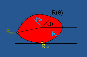
Consider a 2D convex object that has only one stable and one unstable equilibrium point. Define a function, R(ɵ), that is the distance of the perimeter away from the centre of gravity as shown in the figure on the left. The function depends on the angle ɵ (measured in radians) around the centre of gravity and so as ɵ increases from 0 to 2π the function, R, will do one revolution of the shape.

Now consider the graph of R. By assumption there are only two equilibria, one stable and one unstable, thus, the corresponding graph has just one maximum and one minimum, as shown in the figure on the right. This is how the equilibria where defined last week.

Suppose we now drop a horizontal line across the graph. In particular let the points at which the horizontal line touches the graph be separated by an angular distance of π radians. This will correspond to a straight cut through the shape. Call this corresponding value R0.

By definition everything above this horizontal would be the part of the shape that is further than R0 away from the centre of gravity and everything below would the part of the shape closer than R0 to the centre of gravity. This means that one half of the shape would be bigger than the other half, and, thus, heavier. But by definition the cut goes through the centre of gravity and so each side weighs the same. As we come to a contradiction, our original hypothesis (that such a shape exists) must be wrong.
________________________________________________________________
________________________________________

Answers

The cube has 6 stable equilibria; one on each of the flat faces, as shown.
The cube has 5 stable equilibria; one on each of the flat faces, as shown.
The sliced cylinder only has 1 stable equilibrium. However, it is not a shape that satisfies our need because it has 3 unstable equilibria; one on the top of the cylinder and one at each of the tips.

Monday, 7 January 2013

Sense and instability

Figure 1. A worried little weeble.
Did you ever have set of weebles? I did. They were wonderful little toys that lived up to their advertising slogan of “weebles wobble, but they don’t fall down”. The whole premise was that you got a set of several small plastic egg shaped characters (as seen in Figure 1) that would always wobble back to an upright position, no matter what position you started them from. As you can imagine hours of fun could be had with these little things.

The toy's mechanism is very simple. The bottom of the weeble is much heavier than the rest of the body, this means its centre of gravity is very low. Due its egg shaped body the weeble will always wobble such that its centre of gravity is at its lowest point. The applet below shows how this idea works [1]. On the left shape click on the red star which is the centre of mass and move it around the shape. The effect can be seen in the shape on the right. The shape on the right can then be grabbed and started from different initial points. However, it will always evolve to a stable point.


Why am I talking about weebles? Well, they are a really nice way of demonstrating how mathematicians understand equilibrium points, stability and instability. Although theoretically if a body was placed at its equilibrium points nothing further would occur, we know that physically we cannot be that accurate. Thus, equilibrium points can then be separated (generally) into stable and unstable points [2]. Thankfully, the mathematical notion of stability accords with our everyday use of the word. A body is stable if given a small push (or perturbation) it returns back to its previous position.
Figure 2. A wobbling weeble.
For a concrete example of this consider Figure 3, which is a schematic diagram of a curved bowl containing some balls. A is a stable equilibrium point; if the ball is given a small push it will return back to A. If the ball is given a big enough push it can roll right over the dividing line into the C position and this is also a stable equilibrium point. Now consider placing a ball at B. Since the bowl is completely flat there B is also an equilibrium point. However, it is an unstable equilibrium point. This is because no matter how small a push the ball is given it will never head back to B, but rather roll to one of A or C. Importantly, stability is only defined at points A, B and C because these are the only equilibrium points.

Figure 3. Illustrating stable and unstable equilibrium points.
A similar idea is applicable to the states of the weeble. When the weeble is upright it is equivalent to the ball being at A or C; the weeble is at a stable equilibrium point. Now suppose you could balance the weeble perfectly on its head, such that the centre of gravity, G, is directly above the flat point of its head, as in Figure 4. This is equivalent to the point B in Figure 2. It is an equilibrium point and, so, theoretically, if placed there, with no perturbation, then the weeble would stay there forever. However, any perturbation, no matter how small, will cause it to flip over and turn the right way up.
Figure 4. Stable and unstable weebles.
In two weeks time I will continue this topic and see what happens when we remove the possibility of weighting the bottom and only depend on the geometry of the object.
________________________________________________________________
________________________________________

[1] All credit of the applet goes to this website: http://l.d.v.dujardin.pagesperso-orange.fr/ct/cusp.html

[2] Note that there are also saddle points and centres but we’re not going to talk about them as they’re special cases that few people care about. Also, the stable and unstable points could each be further split up into oscillatory and non-oscillatory points but again we’re going to ignore this complexity.